 |
| Breadboard |
What’s in a Name?
When you picture a breadboard in your head, you may envision a big piece of wood and a large loaf of freshly baked bread. You wouldn’t be too far off either.
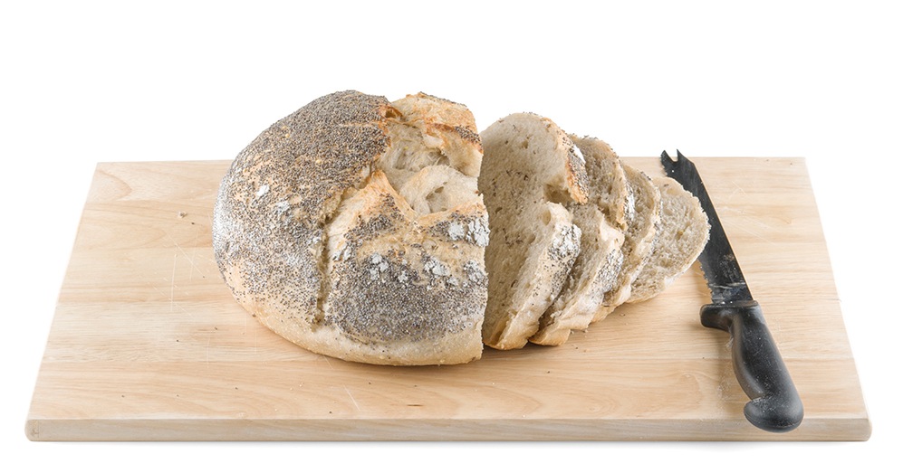 |
| Bread on a breadboard |
So why do we call this electronic “circuit builder” a breadboard? Many years ago, when electronics were big and bulky, people would grab their mom’s breadboard, a few nails or thumbtacks, and start connecting wires onto the board to give themselves a platform on which to build their circuits.
 |
| Circuit on an “original” breadboard |
Since then, electronic components have gotten a lot smaller, and we’ve come up with better ways to connect circuits, making moms all over the world happy to have their breadboards back. However, we are stuck with the confusing name. Technically, these are still breadboards, but this discussion is going to be on modern, “solderless” breadboards.
Why Use Breadboards?
An electronics breadboard (as opposed to the type on which sandwiches are made) is actually referring to a solderless breadboard. These are great units for making temporary circuits and prototyping, and they require absolutely no soldering.
Prototyping is the process of testing out an idea by creating a preliminary model from which other forms are developed or copied, and it is one of the most common uses for breadboards. If you aren’t sure how a circuit will react under a given set of parameters, it’s best to build a prototype and test it out.
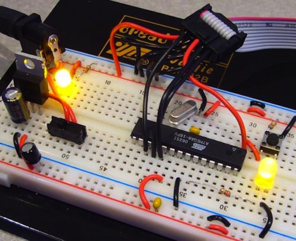 |
| A circuit built on a solderless breadboard |
For those new to electronics and circuits, breadboards are often the best place to start. That is the real beauty of breadboards–they can house both the simplest circuit as well as very complex circuits. As you’ll see later in this tutorial, if your circuit outgrows its current breadboard, others can be be attached to accommodate circuits of all sizes and complexities.
Another common use of breadboards is testing out new parts, such as Integrated circuits (ICs). When you are trying to figure out how a part works and constantly rewiring things, you don’t want to have to solder your connections each time.
As mentioned, you don’t always want the circuit you build to be permanent. When trying to duplicate a customer’s problem, SparkFun’s Technical Support team will often use breadboards to build, test, and analyze the circuit. They can connect the parts the customer has, and once they’ve gotten the circuit setup and figured out the problem, they can take everything apart and put it aside for the next time they need to do some troubleshooting.
Anatomy of a Breadboard
The best way to explain how a breadboard works is to take it apart and see what’s inside. Using a smaller breadboard it’s easier to see just how they function.
- Terminal Strips
Here we have a breadboard where the adhesive backing has been removed. You can see lots of horizontal rows of metal strips on the bottom of the breadboard.
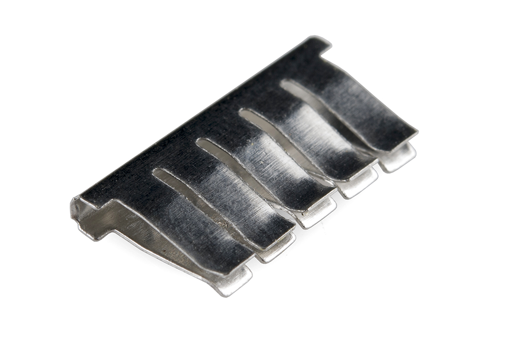 |
| A single strip of conductive metal removed from the above breadboard. |
The tops of the metal rows have little clips that hide under the plastic holes. These clips allow you to stick a wire or the leg of a component into the exposed holes on a breadboard, which then hold it in place.
Once inserted that component will be electrically connected to anything else placed in that row. This is because the metal rows are conductive and allow current to flow from any point in that strip.
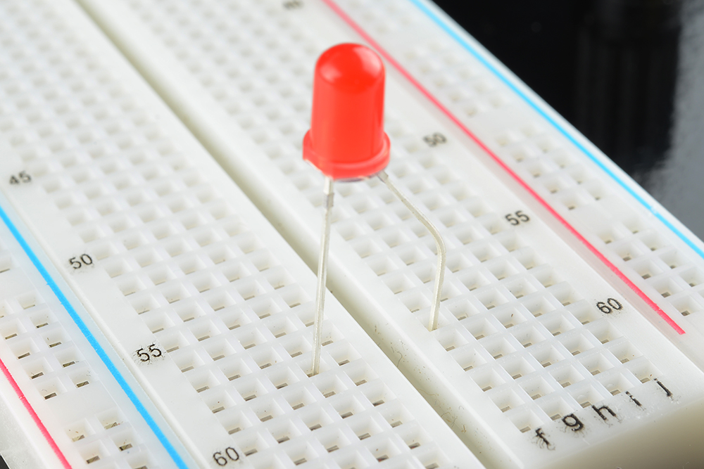 |
| An LED inserted into a breadboard. Notice how each leg of the LED is placed on either side of the ravine. This prevents the connections to the LED from being shorted. |
Notice that there are only five clips on this strip. This is typical on almost all breadboards. Thus, you can only have up to five components connected in one particular section of the breadboard. The row has ten holes, so why can you only connect five components? You’ll also notice that each horizontal row is separated by a ravine, or crevasse, in the middle of the breadboard. This ravine isolates both sides of a given row from one another, and they are not electrically connected. We’ll discuss the purpose of this in just a bit, but, for now, just know that each side of a given row is disconnected from the other, leaving you with five spots for components on either side.
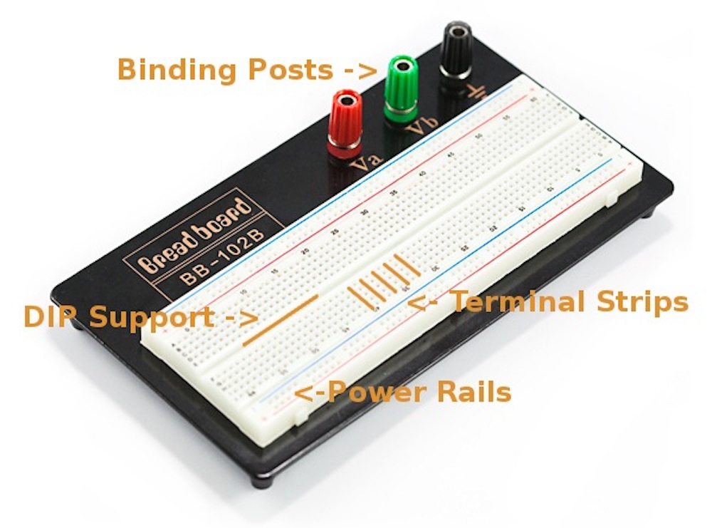
- Power Rails
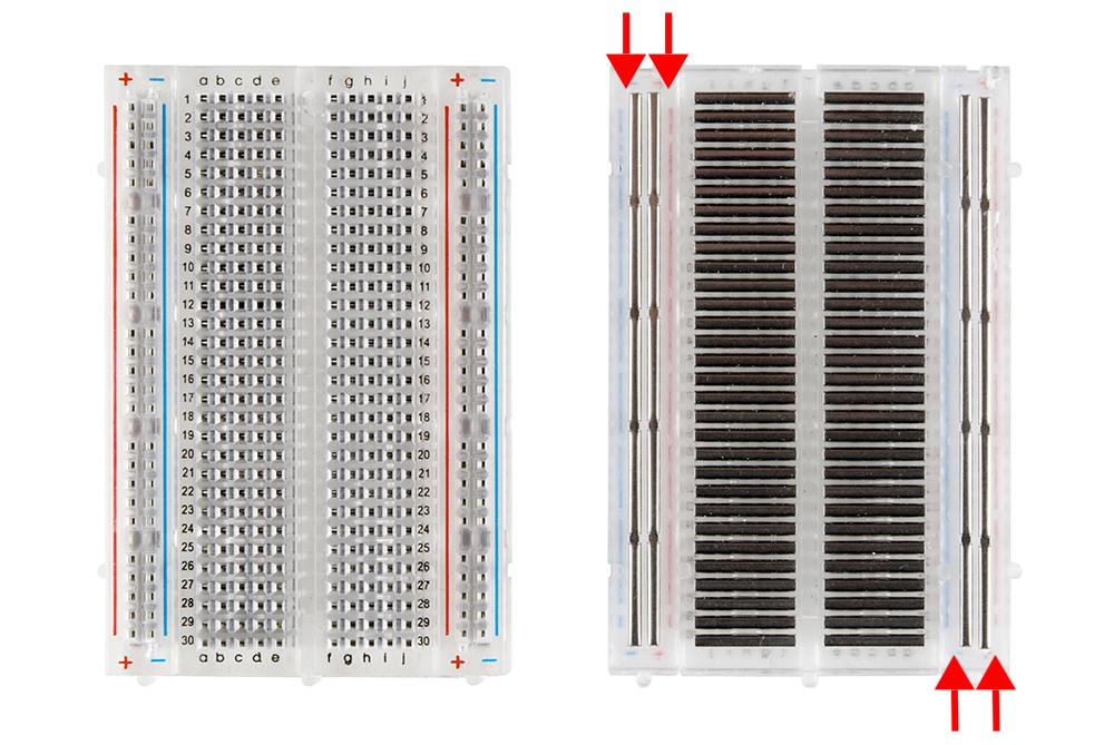 |
| A medium-size breadboard with the adhesive back removed to expose the power rails. |
Now that we’ve seen how the connections in a breadboard are made, let’s look at a larger, more typical breadboard. Aside from horizontal rows, breadboards usually have what are called power rails that run vertically along the sides.
These power rails are metal strips that are identical to the ones that run horizontally, except they are, typically*, all connected. When building a circuit, you tend to need power in lots of different places. The power rails give you lots of easy access to power wherever you need it in your circuit. Usually they will be labeled with a ‘+’ and a ‘-’ and have a redand blue or black stripe, to indicate the positive and negative side.
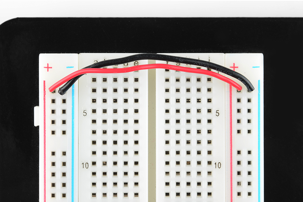 |
Two jumper wires used to connect the power
rails on both sides.
Always attach the ‘+’ to ‘+’ and the ‘-’ to ‘-’.
|
It is important to be aware that the power rails on either side are not connected, so if you want the same power source on both sides, you will need to connect the two sides with some jumper wires. Keep in mind that the markings are there just as a reference. There is no rule that says you have to plug power into the ‘+’ rail and ground into the ‘-'rail, though it’s good practice to keep everything in order.
- DIP Support
 |
| Two DIP ICs, the LM358 (top), a very common op-amp, nd the ever-popular ATMega328 microcontroller (bottom). |
Earlier we mentioned the ravine that isolates the two sides of a breadboard. This ravine serves a very important purpose. Many integrated circuits, often referred to as ICs or, simply, chips, are manufactured specifically to fit onto breadboards. In order to minimize the amount of space they take up on the breadboard, they come in what is known as a Dual in-line Package, or DIP.
These DIP chips (salsa anyone?) have legs that come out of both sides and fit perfectly over that ravine. Since each leg on the IC is unique, we don’t want both sides to be connected to each other. That is where the separation in the middle of the board comes in handy. Thus, we can connect components to each side of the IC without interfering with the functionality of the leg on the opposite side.
- Rows and Columns
You may have noticed that many breadboards have numbers and letters marked on various rows and columns. These don’t serve any purpose other than to help guide you when building your circuit. Circuits can get complicated quickly, and all it takes is one misplaced leg of a component to make the entire circuit malfunction or not work at all. If you know the row number of the connection you are trying to make, it makes it much
Are there different kinds of breadboards?
 Modern breadboards are made from plastic, and come in all shapes, sizes, and even different colors. While larger and smaller sizes are available, the most common sizes you will probably see are "full-size," "half-size," and "mini" breadboards. Most breadboards also come with tabs and notches on the sides that allow you to snap multiple boards together. However, a single half-sized breadboard is sufficient for many beginner-level projects.
What is inside a breadboard?
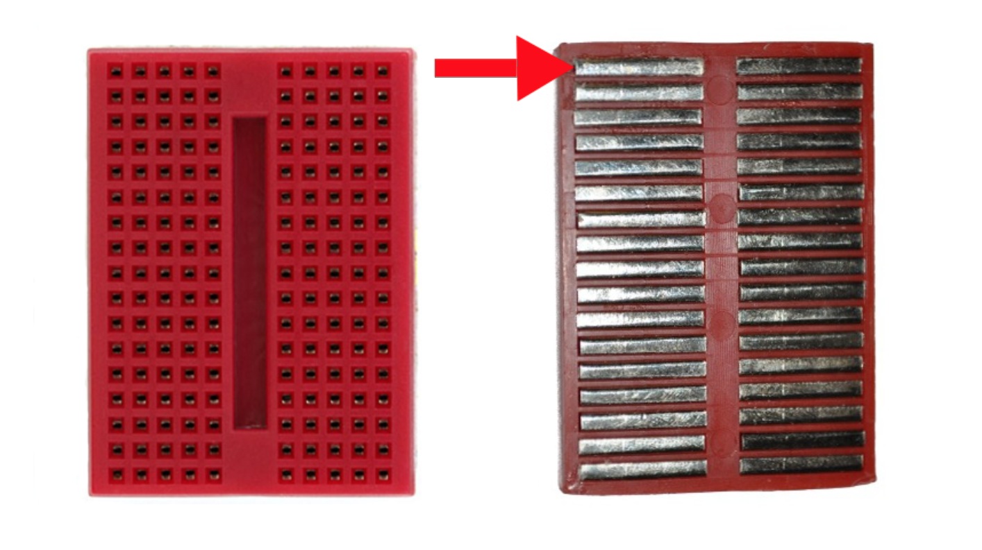
The leads can fit into the breadboard because the inside of a breadboard is made up of rows of tiny metal clips. This is what the clips look like when they are removed from a breadboard.


When you press a component's lead into a breadboard hole, one of these clips grabs onto it.
Some breadboards are actually made of transparent plastic, so you can see the clips inside.
Some breadboards are actually made of transparent plastic, so you can see the clips inside.
Most breadboards have a backing layer that prevents the metal clips from falling out. The backing is typically a layer of sticky, double-sided tape covered by a protective layer of paper. If you want to permanently "stick" the breadboard to something (for example, a robot), you just need to peel off the paper layer to expose the sticky tape underneath. In this picture, the breadboard on the right has had its backing removed completely (so you can see all the metal clips). The breadboard on the left still has its sticky backing, with one corner of the paper layer peeled up.

Note how all holes in the selected row are connected together, so the holes in the selected column. The set of connected holes can be called a node:

To interconnect the selected row (node A) and column (node B) a cable going from any hole in the row to any hole in the column is needed:
 Now the selected column (node B) and row (node A) are interconnected


Note how all holes in the selected row are connected together, so the holes in the selected column. The set of connected holes can be called a node:

To interconnect the selected row (node A) and column (node B) a cable going from any hole in the row to any hole in the column is needed:

Now the selected column (node B) and row (node A) are interconnected

Any wire we can used here?
ReplyDeleteYou can use any wire, however, if you've ever tried to use stranded wire in a breadboard or some other type of socket, you'll know what a pain it can be. Loose strands of wire may have even short circuited one of your projects before. Next time try coating the stranded wire with a little bit of solder to keep the ends sticking together.
DeletePros and Cons of Bread Board to PCB and does a breadboard have a similarity to PCB?
ReplyDeleteA breadboard is the way to go for prototyping effects and in breadboarding you can easily update your circuit while in Printed circuit board is not easy to repair when damaged.
DeleteYes they are similar but not the same.A Breadboard is used to make sure a circuit works correctly without having to solder in the components. With a printed circuit board you need to solder in the components and you cant easily remove them. So yes it will work but you have to make sure you get the components in right the first time.
maam, how can i test my breadboard if it is good?
ReplyDeleteIf you want to start making a basic electronics project by placing power sources and such on a breadboard, you should make sure that the breadboard will work first. You can do this by using a multimeter to perform a continuity test on your breadboar.
ReplyDeleteWhat is the common reason why breadboard is so easy to be damaged? It is based on my experience ma'am :) I thought my circuit was wrong but at the end i noticed that the problem was in my breadboard.
ReplyDeleteI think the common reason is that we did'nt really place practice the proper wiring. Be prepared to use them with care, take care of how you insert wires into them and be realistic in what you expect of them.
DeleteHere are some tips on how you can take care of you breadboard:
NEVER plug larger leaded components into them. One forced insertion may weaken the spring at that point forever. If you want to use larger leaded components, solder a small extension of thinner wire onto them. The venturesome could wrap many turns of wire around a component lead to remove the need to solder. This would often work well - but YMMV*, as always.
Use smooth plated wires without nicks. Do not use bar copper wire which can corrode. Do not use abrasive wires (nicked etc)
Be aware that the strips have high capacitance between adjacent rows - circuits that are adversely affected by a picoFarad or few of interstrip coupling are not good candidates.
Do not pass high currents through the breadboard. It may cause no problems now or in future. Or may.
Be aware that wires may pull out or short or conspire against you.
Components with very small diameter leads may make poor contact.
Ma'am can you give us tips in using the wires as connectors in breadboarding?
ReplyDeletehere are the tips for wiring a breadboard:
Delete• Color-code your 22-24 gauge solid wires for different functions. Red wire is commonly
used for power (+5V), while black is often used for ground. Yellow, white, blue, grey,
etc. can be used for signal wires.
• Strip about 1/4 to 3/8 inch of insulation from the wire, and cut the end of the wire on a 45
degree angle for easy insertion into the breadboard. Push the wire in as far as it will go to
insure a good connection.
• Use the banana plug connectors to provide power to the board. Short pieces of color
coded wire can be clamped under the banana plug and routed to the designated “bus” on
the breadboard.
• Avoid the use of “alligator” clips (particularly the uninsulated type), since they are prone
to electrical “shorts” and other mis-connections.
If two or more wires are routed together (such as a signal and ground wire), either twist
or tape the wires together at several locations along their length. This will reduce the
effects of electrical “noise,” allow easier debugging of circuits, and reduce the chances of
wires being pulled loose from the circuit board.
Ma'am ano po yung pinaka purpose ng breadboard ?
ReplyDeleteThe purpose of the breadboard is to make quick electrical connections between components- like resistors, LEDs, capacitors, etc- so that you can test your circuit before permanently soldering it together.
DeleteThis comment has been removed by the author.
ReplyDeleteWhat are the different brands of breadboard we can find?
ReplyDeletethese are some brands electronic product that offers different types of breadboard
ReplyDeleteGlobal Specialties Premium Proto-Board®
Elecrow
Elenco
Is it possible to clean the inner part of the breadboard?? if yes, How?
ReplyDeleteYes, you can clean it by just simply removed the rubber part of the breadboard and then remove the unnecessary wire in clips to avoid shorted connection.
ReplyDeleteWhat is the common problem that we may encounter when using breadboard?
ReplyDeleteCommon Breadboard Problems
DeleteDon't insert insulated portion of wire into hole
Intermittent contact can occur when wire is loose in clip
Use 22 gauge wire for best contact in clip
Using 22 gauge and stripping enough insulation will prevent you from accidentally pushing insulation into the clip
Don't force large wires and component leads into the breadboard, this will stretch the clips
Test contacts by inserting 22 gauge wire and pulling on the wire (should be able to lift board)
If a lot of holes are loose with a 22 gauge wire, it's time to replace the board
Hi ma'am. In making a circuit, do I have to used breadboard before I create a prototype? Why?
ReplyDeleteNot necessarily, it depends if you want to test your circuit before soldering it to the PCB. If you use breadboard first you can easily check your connection and you can be able to avoid trial and error process in soldering to the PCB.
ReplyDeletewhy do we need to use breadboard '?
ReplyDelete..mam may iba po bang type ng breadboard?..o breasdboard na gawa sa ibANg material?
ReplyDeleteThere are various types of breadboard.Breadboard can be found in various sizes and functions.Early amateur radio hobbists used cutting board for bread to prototype there radios thus the name breadboard came.Some breadboards got built-in powersupply,some got power supply rail and some got only the prototyping section.
Delete